
- October 23, 2026
- Posted by: wellcoindustries
- Category: Geogrid
Install geogrid in a segmental retaining wall at the elevations, lengths, directions and facing connections specified for that project. Prepare the supporting fill, place and secure the grid using the applicable wall-system instructions, remove slack, and check the exposed layer before backfilling. Protect the grid while placing and compacting fill, then repeat at the next specified elevation. These steps follow a project design; they do not determine reinforcement requirements. [1][2][3]
This guide helps contractors and project buyers organize those installation checks. If the reinforcement decision is still open, start with whether your retaining wall needs geogrid.
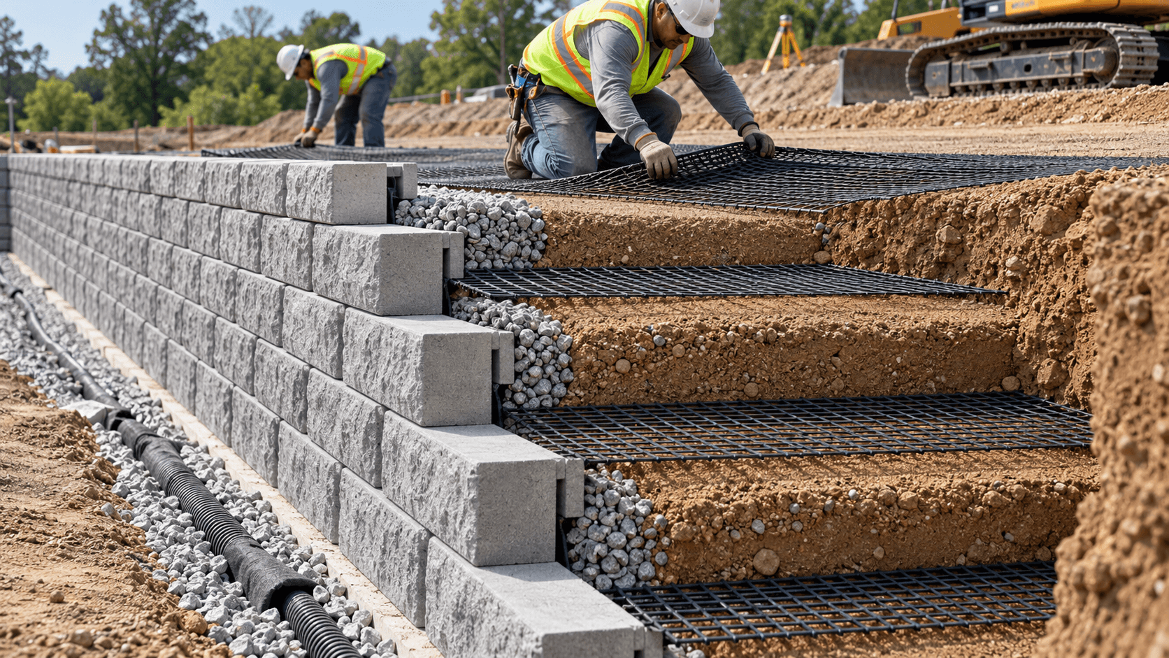
1. Match the delivered grid to the construction documents
Bring the current wall drawings, reinforcement schedule and installation instructions together before cutting material. Identify the wall unit and specified grid, then compare the delivery labels with the material requirement. Keep any proposed substitution separate from the accepted design. Equal roll size, nominal tensile strength or a similar grid label does not establish interchangeability; the proposed material still needs acceptance for the wall system and project requirements. [2]
Find the first reinforcement elevation, required length, direction and connection detail on the drawings. If a detail is missing or the supplied material differs, ask the responsible designer for a decision before installing that layer. CMHA directs users to product-specific information for the blocks and geosynthetics as well as evaluation of site conditions. [1]
A roll’s width or a uniaxial/biaxial label is not a complete installation instruction. Our guide to geogrid types and specification fields explains the material-selection question; the project documents establish the installation requirement.
2. Prepare the wall and fill to the specified layer elevation
Build the facing and place the specified drainage aggregate and compacted backfill up to the reinforcement elevation. Establish the supporting surface before laying grid across it. VERSA-LOK’s installation sequence places this preparation ahead of reinforcement placement. [2]
Check the layer location against the drawing and the actual wall course. Do not substitute a remembered rule such as “every other course” for the reinforcement schedule. A difference in unit height, wall section or project detail can change where a layer belongs.
Before placement, clear the block surface and check that the prepared area can accommodate the specified reinforcement length. If the excavation, utility location or available space prevents that layout, resolve the conflict rather than shortening the grid on site.
3. Verify direction and required length before cutting
Identify the required reinforcement direction and length from the project detail and the instructions for the actual grid. Confirm both before cutting. Follow the applicable system instructions on whether to precut the material or unroll it into position and then cut to length. VERSA-TECH describes both options for its Standard system; CornerStone links correct orientation, strength and length to its design. [4][6]
Do not turn the roll simply to reduce cutting waste. Wall-system instructions are not interchangeable: VERSA-LOK describes its VERSA-Grid roll direction as the strength direction, while Allan Block gives different placement instructions for its named residential grid and wall collections. Neither instruction establishes the correct direction for another product. [2][3]
Where the direction marking or product identity is unclear, hold that material aside and request clarification. Appearance alone is insufficient to resolve the match.
4. Form the specified facing connection and remove slack
Position the front edge as the applicable connection detail requires. Install the next units and any specified connectors in the sequence for that wall system. Check the facing alignment while securing the grid.
Connection details differ. VERSA-LOK describes a pin connection for its units; CornerStone describes engagement through its SecureLugs and gravel core. Do not substitute one system’s front-edge position or connection method for another. [2][4]
Remove slack and folds using the applicable system procedure. Pull the grid taut enough to remove slack without moving the wall units or disturbing the facing alignment. Recheck alignment after tensioning. VERSA-TECH and CornerStone emphasize keeping the facing in position; these instructions do not establish a universal tensioning force for every grid. [4][6]
If the connection cannot be formed as detailed, stop before covering it. Record the location and discrepancy so the designer can address the actual condition.
5. Resolve corners, curves and obstructions before covering
Check the detail for the particular turn or obstruction before treating it as a repeat of a straight section. A corner can change how reinforcement from adjacent wall runs is arranged.
VERSA-LOK requires special placement procedures for curves and corners and directs unresolved details to the final wall designer. Its instructions also distinguish separated overlapping layers from grid placed directly against grid. Do not invent an overlap or cut a slot around an obstruction without an applicable detail. [2]
Keep the affected area accessible while obtaining a clarification. A photograph should show the wall location and proposed arrangement, not just a close-up of unidentified mesh.
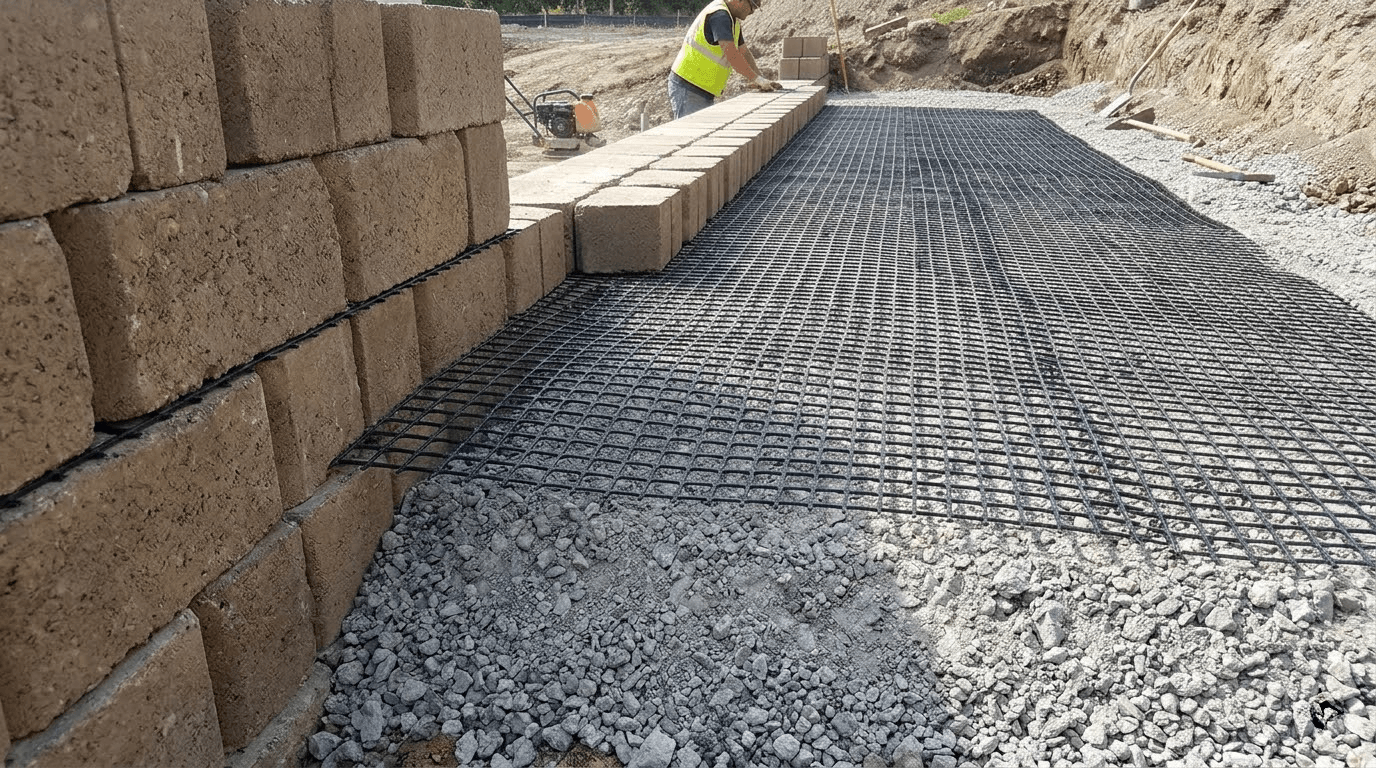
6. Protect the grid during backfill and compaction
Inspect the exposed grid for folds, displacement and visible damage before fill hides it. If material is damaged, identify the affected piece and obtain an accepted disposition; do not improvise a repair or assume extra overlap restores it.
Place the specified fill so that the grid remains aligned and free of slack. Use the project’s lift thickness, compaction requirements and equipment restrictions together with the applicable system instructions. Check for movement as the fill operation begins. [3][4]
Do not drive or compact directly on exposed geogrid. Establish the required protective cover before equipment access, and follow the specified restrictions near the wall face. The required cover and operating limits must come from the applicable documents, not a universal value taken from another system’s guide. [2][3][4]
Repeat the placement and checks at each scheduled layer. If site conditions or the proposed equipment differ from the accepted construction requirements, resolve the difference before proceeding in that area.
Keep a record before each layer is concealed
Use a separate record for each reinforcement location. The following card organizes evidence for the project’s required inspection; it does not replace the specified acceptance process. CMHA describes inspection as a way to verify construction against the design and specified materials. [5]
| Record field | What to enter or attach |
|---|---|
| Location | Wall identification, section or station, course and reinforcement elevation |
| Controlling requirement | Drawing/detail reference and revision, reinforcement designation and applicable installation instructions |
| Material and placement | Delivery or roll identification; checked direction, length and facing connection |
| Before-cover evidence | Dated photos tied to the location, showing the connection and exposed reinforcement arrangement |
| Difference and disposition | The observed discrepancy, clarification reference and accepted action; keep unresolved items open |
| Inspection and next operation | The check required by the project, its result and responsible person’s record, followed by the applicable backfill/compaction record |
Retain the record with the project documents. A photo alone cannot demonstrate reinforcement properties or compaction acceptance. Finish the required checks while the work remains visible, rather than trying to reconstruct them after backfilling.
Prepare the material inquiry from the accepted requirement
Once the project specifies the reinforcement, review our geogrid product options and send our team your requirements. Include the specified material, relevant drawings or property requirements, roll dimensions, quantity and delivery location. Contact us to confirm the product options for your inquiry. Keep acceptance of any proposed material or installation change with the responsible wall designer.
References
- CMHA, Segmental Retaining Wall Installation Guide, SRW-MAN-003-10, public introduction and scope. General guidance and product-specific instructions.
- VERSA-LOK, Geogrid, “How to Install VERSA-Grid Soil Reinforcement,” steps 1–8. Instructions apply to the stated system.
- Allan Block, Geogrid Installation, Residential Installation Manual, pp. 26–27. Instructions apply to the named wall collections and reinforcement.
- CornerStone, Geogrid Retaining Wall Installation, CornerStone 100 system, steps 2–4.
- CMHA, Inspection Guide for Segmental Retaining Walls, SRW-TEC-008-12, introduction and inspection scope.
- VERSA-TECH Academy, Standard — Geogrid, placement/cutting options and slack removal for the VERSA-LOK Standard system.